
Custom Glass Filled PTFE Tube Properties and Applications
2026-11-02
When standard PTFE tubing falls short under demanding mechanical loads, engineers often turn to custom glass filled PTFE tube solutions. This reinforced variant combines the inherent chemical resistance and low friction of PTFE with dramatically improved compressive strength and dimensional stability. At TAIFNO, we specialize in tailoring these tubes to exacting specifications—from glass fiber content and wall thickness to precise inner diameters—so you don't have to compromise between performance and manufacturability. In this post, we'll break down what makes glass filled PTFE different, where it excels, and how custom geometries can solve problems that off-the-shelf tubing simply cannot.
Inside the Composite: Glass Fibers Meet PTFE
At the heart of many high-performance bearings and bushings lies a blend that seems almost contradictory: glass fibers woven into PTFE. PTFE alone offers an exceptionally low coefficient of friction and remarkable chemical resistance, but it lacks the mechanical strength to handle heavy loads or maintain shape under pressure. Glass fibers, on the other hand, bring stiffness, compressive strength, and dimensional stability—but they’re abrasive and would quickly wear against a mating surface if left unprotected. The composite works because the PTFE encapsulates each fiber, reducing friction while the fibers carry load. The result is a material that slides smoothly yet resists deformation, making it ideal for applications like automotive suspension joints or industrial machinery pivots where both low friction and high load capacity are non-negotiable.
The manufacturing process itself is a study in careful balance. Short glass fibers, typically 10 to 25 percent by weight, are mixed with PTFE powder before compression molding or ram extrusion. Too little fiber and the composite creeps under load; too much and the surface becomes rough, accelerating wear on the mating shaft or plate. During molding, the fibers tend to align perpendicular to the pressing direction, which means engineers must consider fiber orientation when designing a part—orientation parallel to the sliding surface maximizes load support, while perpendicular orientation can lead to uneven wear. The interface between fiber and PTFE also matters: without proper surface treatment, micro-voids can form, allowing moisture or debris to collect and weaken the bond over time. Advanced formulations now use silane coatings on the glass to improve adhesion and extend service life, especially in wet or corrosive environments.
Yet the pairing isn’t for every application. PTFE-glass composites excel in dry sliding conditions, often outperforming metal-backed bushings where lubrication is impossible or undesirable—think food processing equipment, marine deck hardware, or aerospace control linkages. However, the glass fibers make the composite slightly harder than pure PTFE, which can transfer wear to a softer mating surface, such as anodized aluminum or some stainless steels. Designers sometimes add a thin PTFE-rich layer on the sliding face to retain the low friction while keeping the fiber-reinforced core for strength. This layered approach—a composite within a composite—reflects how material science often works: not by finding one perfect ingredient, but by carefully combining weaknesses into strengths. When glass fibers meet PTFE, the result is neither slippery nor rigid alone, but something far more useful: a bearing that quietly carries load, shrugs off chemicals, and keeps moving long after metal alternatives would have seized.
Dimensional Stability Without Sacrificing Flexibility
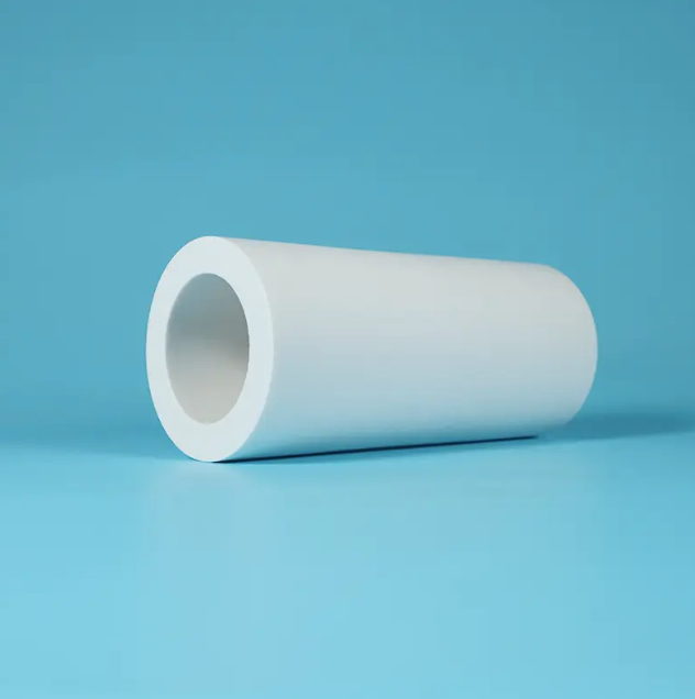
Achieving dimensional stability often comes at the cost of rigidity, but modern materials prove that you can have both. The key lies in engineered polymer blends and precision manufacturing that lock in shape retention while allowing controlled flex. Whether it's a gasket that must hold its form under pressure or a wearable device component that needs to bend with the body, the right material prevents warping, shrinking, or stretching over time without turning brittle. This balance ensures parts remain reliable across temperature swings and repeated use.
One practical approach is to combine a stable core structure with flexible outer layers, or to use additives that reduce thermal expansion without hardening the matrix. The result is a material that maintains critical dimensions during assembly and operation, yet still absorbs impact and movement. Designers no longer have to choose between a part that stays true to size and one that can survive real-world flexing—they can specify a single solution that delivers both.
When Off-the-Shelf Tubes Fall Short
Mass-produced tubes rarely arrive with the tight matching that a well-designed push-pull output stage expects. A pair of EL84s bought from the same shelf can differ in transconductance by 10–15%, which pushes one side harder, raises distortion, and shortens tube life. The problem gets worse in circuits running high plate voltages or fixed bias, where even small mismatches drift further as the tubes age.
Microphonics and noise are another common failure point. In high-gain phono or microphone stages, an off-the-shelf 12AX7 may ring at certain frequencies or pick up mechanical vibration from the chassis. Selecting a quiet, low-microphony tube often means testing a dozen samples or hunting for specific NOS constructions, because the generic datasheet never tells you how a tube will behave in your circuit.
Then there's thermal drift and gas leakage. Current-production tubes sometimes develop grid emission or slight gas after a few hundred hours, causing bias points to wander. That's rarely a problem in a guitar amp that gets retubed often, but in a restoration or a piece of lab equipment it can be a real headache. When the application demands long-term stability, off-the-shelf tubes simply don't have the quality control to back up their spec sheets.
Surviving Aggressive Chemicals and High Heat
A pump housing that shrugs off hydrochloric acid at room temperature can still turn brittle after a few weeks of exposure to hot sulfuric acid and trace chlorides. The failure rarely comes from a single chemical attack; it comes from the combination of corrosive media, thermal expansion, and repeated cycling between process extremes.
Resins and coatings that survive these conditions do more than resist dissolution. They need low porosity, stable cross-linking, and enough flexibility to handle rapid temperature swings without cracking. In practice, a material that works well in a lab immersion test can fail quickly on a plant floor where steam purges follow solvent rinses and the same flange sees both oxidizing and reducing conditions in one shift.
The most reliable installations treat chemical and heat resistance as a system property, not a single rating. Gaskets, linings, and structural layers are selected together, with attention to thermal gradients and condensation zones where aggressive vapors collect. When those details are overlooked, the first sign is often a small leak at a fitting—long before the bulk material shows any visible damage.
Wear Resistance That Extends Service Life
In heavy-duty machinery, the difference between a part lasting six months and six years often comes down to a single property: how well its surface shrugs off friction. Components that grind, slide, or roll under load slowly lose material with every cycle. By selecting alloys with high hardness and optimizing the microstructure, engineers can create surfaces that essentially refuse to shed particles, locking in dimensional accuracy far longer than conventional materials.
Surface treatments take this even further. Thermal spray coatings, nitriding, or laser cladding build a sacrificial layer that takes the beating while the core remains intact. It's not just about adding hardness — it's about forming a gradient that prevents cracks from migrating inward. The result is a wear face that polishes itself under use instead of roughening, which actually reduces friction over time rather than increasing it.
For operators, the payoff shows up in fewer unplanned stops. A chute liner that used to need replacement every quarter can now survive multiple seasons. Bearings that once developed play within hundreds of hours keep their preload for thousands. This isn't just extending service life on paper; it means less downtime, fewer spare parts to stock, and a maintenance schedule that finally matches the rhythm of the whole production line.
Matching Glass Content to Specific Load Profiles
Glass selection only works when the actual load profile drives the decision. A vertical facade in a hurricane zone faces short, intense wind pressures and flying debris, while a sloped atrium roof accumulates snow and drains meltwater unevenly. Treating those as the same condition leads to either brittle failure or needless thickness. Matching glass content starts with mapping the real stress history of the opening, not the nominal design load from a table.
Once the profile is clear, composition choices become more specific. Laminated interlayers earn their place when post-breakage retention matters, not as a default upgrade. Tempering helps with thermal gradients and edge strength but shifts break patterns. Low-iron glass can cut solar absorption enough to change deflection behavior on large spans. Each layer has a job, and it's only justified if the load profile shows that job exists.
The final check should use the project's own data. Wind tunnel records, snow drift surveys, or footfall counts on walkable glass reveal where stress peaks and how often it repeats. Adjust the stack-up until predicted stress stays within the safety margin without adding redundant mass. That kind of iteration keeps the glass efficient and the structure honest.
FAQ
A glass filled PTFE tube is made from PTFE resin compounded with glass fibers, usually between 15% and 25% by weight. The glass makes the material stiffer, reduces cold flow under load, and improves wear resistance. In exchange, it gives up some flexibility and a bit of chemical inertness compared to virgin PTFE.
They show up frequently in chemical processing, oil and gas, food and pharmaceutical, water treatment, and electrical insulation. Those fields need tubing that holds its shape under pressure and resists deformation without using metal components.
Glass filled PTFE generally keeps a continuous service ceiling around 260°C (500°F), which is close to unfilled PTFE. The real advantage at high temperature is lower thermal expansion and less creep, so dimensions stay more predictable.
Yes. The added glass stiffens the material enough to cut cleanly without burring, so diameters can often be held within ±0.05 mm. This makes secondary operations like flaring, grooving, or precision facing much easier than with virgin PTFE.
Most acids, bases, and solvents won’t touch glass filled PTFE, but it is more vulnerable to hydrofluoric acid and molten alkali metals because the glass fibers can be attacked. For routine chemical service, the difference is negligible.
Glass offers a solid balance of stiffness and cost without adding electrical conductivity. Carbon is better for static dissipation, and bronze helps heat transfer but may leave metallic traces. Glass is the default when you need a non-conductive, dimensionally stable structural tube.
The main drawbacks are lower elongation and impact strength, higher abrasiveness against soft mating surfaces, and slightly reduced dielectric strength. It is not the best pick for ultra-flexible tubing or high-purity semiconductor lines.
Provide the exact inner diameter, outer diameter or wall thickness, glass percentage (commonly 15%, 20%, or 25%), and total length. If you share the working pressure and temperature, the fabricator can confirm whether the wall thickness is adequate.
Conclusion
Glass-filled PTFE tubing takes an already versatile fluoropolymer and gives it a structural backbone. Inside the composite, short glass fibers interlock with the PTFE matrix, dramatically reducing cold flow and creep under load while preserving the low-friction, non-stick surface that pure PTFE is known for. The result is dimensional stability that holds tight tolerances even when the tube is flexed, cut, or installed in cramped spaces. This matters most when off-the-shelf tubes fall short—standard PTFE often deforms under compression or thermal cycling, leading to leaks or misalignment. Custom glass-filled versions are tailored to the exact inner and outer diameters, wall thickness, and fiber orientation a specific assembly demands, so engineers don't have to compromise on fit or performance.
Beyond mechanical upgrades, these tubes thrive in aggressive chemical and high-temperature environments. The PTFE base resists nearly all industrial solvents, acids, and bases, while the glass filler adds heat deflection capability, allowing continuous service at temperatures that would soften many other plastics. Wear resistance is another standout: the glass fibers reinforce the bearing surface, extending service life in dynamic applications such as bushings, seals, and guide tubes. Crucially, glass content can be matched to specific load profiles—from 5% for improved dimensional control in low-load sensing lines to 25% or more for high-wear, high-compression duties. This tunability means a custom tube can be optimized for creep resistance, wear life, or a balance of both, making it a go-to for demanding fluid handling, chemical processing, and instrumentation systems.
Contact Us
Contact Person: Tommy Xiao
Email: [email protected]
Tel/WhatsApp: 8615651509888
Website: https://www.ptfe-factory.com