

Custom High Containment Valves: Ensuring Safety in Critical Processes
2026-11-16
When you're handling potent compounds or sterile intermediates, every connection in your process line either protects your team or puts it at risk. Off-the-shelf valves rarely match the exact pressure, material, and containment demands of critical applications. That's where AVM steps in—engineering custom high containment valves that don't just meet specs, they anticipate failure modes before they happen. In this post, we'll unpack what separates a truly safe valve from a standard one, and why customization isn't a luxury when the margin for error is zero.
When Standard Valves Can't Handle the Pressure (or the Powder)
Standard valves are typically designed for clean liquids or gases at moderate pressures, but once you introduce high-pressure differentials or fine powders, the usual soft-seated ball or globe valves start to fail in predictable ways. Under extreme pressure, an elastomer seat can extrude or deform, causing leaks that only worsen with each cycle. Powders bring their own set of problems: they pack into stem packing, abrade sealing surfaces, and can jam the closure member, leaving operators with a valve that either won't seal or won't move at all.
To keep production running, many plants turn to valves built specifically for these punishing conditions. Metal-seated designs eliminate the soft seal that gets chewed up or blown out, while hardened trim and coatings resist erosion from abrasive particles. For powder service, look for features like purged packing glands, full-bore flow paths to prevent bridging, and self-cleaning seat geometries that scrape away buildup. Pressure spikes also matter—a valve rated for static pressure may not survive rapid cycling or water hammer, so the actuator and body must be matched to the actual dynamic loads, not just the nominal line pressure.
The Hidden Risks of Cross-Contamination in High-Potency Lines
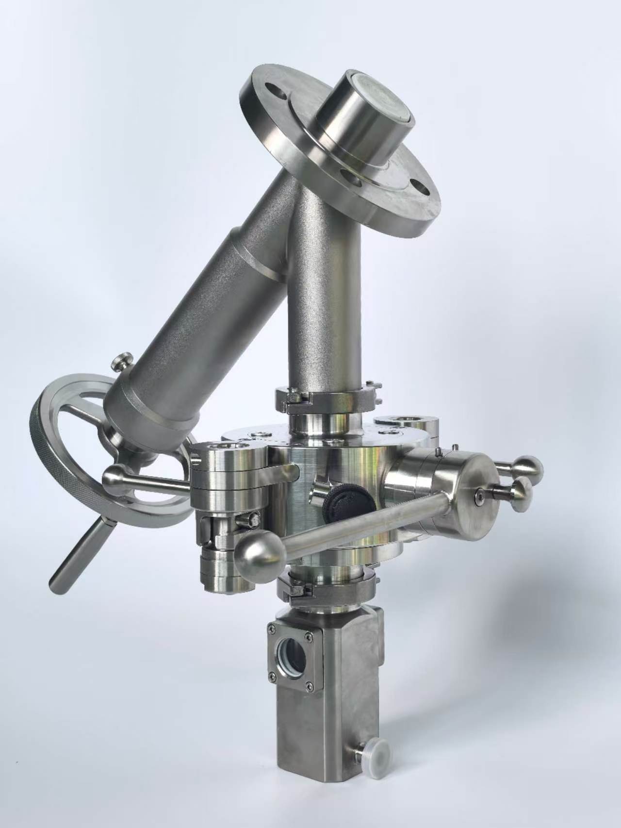
High-potency manufacturing often focuses on visible safeguards—isolators, airlocks, and strict gowning procedures. Yet some of the most dangerous contamination events never announce themselves. They ride along on shared equipment surfaces, linger in the microscopic crevices of transfer ports, or hide within the very cleaning validation data that looks acceptable on paper but fails under real-world variability.
A single overlooked carryover of just a few micrograms of a cytotoxic compound can render an entire batch unsafe. The problem deepens when facilities run multiple products on the same line without fully mapping residue behavior across different solubility profiles. What rinses clean for one molecule may bind stubbornly to stainless steel or elastomer seals for another.
Beyond immediate product failure, cross-contamination in these lines can erode regulatory trust and force costly shutdowns. Operators who rely solely on visual inspection or routine swab tests often miss intermittent contamination caused by maintenance activities, tool sharing, or even compressed air lines that draw particles from adjacent zones.
Designing for Zero Leakage: What Actually Works
The first thing to accept is that zero leakage is not a component you buy, but a path you eliminate. Most leaks in practice come down to joint geometry and assembly, not exotic materials. Look hard at every static seal: a flange with poor bolt spacing will leak no matter what gasket you install. Prefer welded or brazed connections where disassembly is not required. For demountable joints, metal-to-metal seal fittings with a controlled bite—like double-ferrule compression types—consistently outperform elastomer-based designs in thermal cycling. The rule of thumb is simple: reduce the number of sealing interfaces, and treat each remaining one as a potential failure point that must be torqued to a recorded value, not “felt tight.”
Material selection only matters once the geometry is right. If you spec an O-ring, pay attention to surface finish—Ra 0.4 to 0.8 µm on the sealing surface is realistic, not a marketing number. Elastomers like nitrile work fine within their temperature window, but step outside it and you get compression set that quietly opens a leak path. For aggressive media or wide temperature swings, consider spring-energized PTFE seals or fully welded metal bellows. Also avoid mixing stainless steel fittings with carbon steel tubing: the galvanic couple will corrode the seal area long before the bulk material fails. Pick materials that stay dimensionally stable under your actual pressure and temperature, not just the vendor’s datasheet.
Verification is where most “zero leakage” claims fall apart. A bubble test will not find a 1×10⁻⁶ mbar·L/s leak. Use helium mass spectrometry with a sniffer probe on large systems, or a vacuum chamber for small assemblies. Run the test after thermal cycling and pressure cycling, not just on a fresh build. Record a baseline decay curve, then compare it six months later—drift in the curve often reveals a slow degradation mechanism before a leak becomes measurable. If you need continuous assurance, ultrasonic acoustic sensors can catch a developing leak in pressurized gas systems earlier than any pressure gauge. Zero leakage is a process of measurement and re-measurement, not a one-time certification.
Materials That Survive Aggressive Clean-in-Place Cycles
Stainless steel remains the workhorse for process lines facing harsh CIP regimes, but not all grades hold up equally. The real differentiator lies in surface finish and molybdenum content—electropolished 316L with a roughness below 0.4 µm Ra resists caustic and acid attack far better than standard mill finishes. Over time, even premium alloys develop micro-pitting if passivation is neglected, so pairing the right metal with a proper maintenance schedule matters more than chasing exotic materials.
For seals, gaskets, and diaphragms, EPDM and PTFE dominate, yet their longevity depends heavily on concentration and temperature swings. A peroxide-cured EPDM handles sodium hydroxide up to 5% at 80°C without swelling, while PTFE remains inert across most CIP chemicals but can creep under high mechanical load. Silicone, despite its heat resistance, often fails early in aggressive cycles due to poor alkali tolerance—a costly oversight if specified for the wrong seals.
Beyond metals and elastomers, ceramics and engineered plastics are carving out niches. Silicon carbide mechanical seals shrug off both thermal shock and chemical attack, though they demand precise alignment. PEEK and PVDF fittings withstand repeated exposure to nitric acid and hot detergent, but their brittleness requires careful torque control. The key is matching each material not just to the chemical, but to the entire cycle profile—temperature ramps, pressure spikes, and rinse phases all contribute to premature failure as much as the cleaning agents themselves.
Retrofitting an Existing Line Without Sacrificing Containment
Retrofitting an existing production line usually means tearing into a process that was painstakingly validated, and when that line handles potent compounds or sterile products, containment is the last thing you can afford to compromise. The real challenge isn't just bolting on new equipment—it's doing so without breaking the cascade of pressure differentials, HEPA-filtered airflow, and restricted access barriers that keep operators and product safe. Too often, facilities discover that a planned upgrade forces them to shut down adjacent areas or re-qualify entire suites because a single wall penetration altered the room's pressure balance.
One approach that works well is to stage the retrofit in controlled micro-phases, treating each opening or tie-in as a temporary containment boundary. Before any cutting begins, use smoke studies and real-time particle monitoring to map how the existing airflow will respond, then install temporary soft-wall isolators or glovebag enclosures around the work zone. Rather than replacing entire air handlers, many teams find they can preserve the original containment envelope by adding redundant HEPA stages or variable-speed fans to compensate for new duct runs. This keeps the line running on one side while construction proceeds on the other, and it avoids the common mistake of designing the new layout around ideal conditions instead of the actual, slightly degraded state of the facility.
After the physical work is complete, the containment performance must be re-verified under load, not just at rest. Leak testing of seals, pressure decay tests, and biological indicator challenges should be done with product-contact surfaces and utilities in their final configuration. It's also worth retraining operators before handover, because even minor changes to transfer ports or glove positions can break habits and lead to breaches that no engineering control can fully prevent. When done carefully, a retrofitted line can come back online with equal or better containment—often with more intelligent monitoring than it had originally.
From Pilot Scale to Production: Lessons from the Field
The jump from a pilot plant to full-scale production rarely follows the neat projections drawn up in boardrooms. On paper, scaling up looks like a straightforward multiplication of inputs and outputs, but in the field you quickly learn that mixing dynamics change, heat transfer behaves differently, and what worked in a 200-liter reactor can become a bottleneck at 20,000 liters. One of the hardest lessons is that your pilot data can hide variability that only becomes visible when you run continuous shifts with real operators, not just researchers.
Another field-tested truth is that instrumentation designed for a pilot unit often fails under production stress. Sensors that were calibrated weekly now need daily checks, and control loops tuned for gentle ramps can oscillate wildly when feedstock quality shifts. The most successful scale-ups we have seen treat the first production months as an extension of the pilot phase—running statistically designed experiments on the full line, accepting some off-spec batches to map the real operating window, and building in redundancy for the two or three failure points that never showed up at smaller scale.
People make the difference. Operators who ran the pilot often get promoted or moved, and the new production crew may not share the same intuition for borderline conditions. Documenting tacit knowledge is difficult; writing a manual is not enough. We found that pairing a pilot veteran with each production shift for at least six weeks, and encouraging them to log every minor deviation, saves months of troubleshooting later. The field teaches that scaling up is less about engineering perfection and more about adapting to the messiness of real materials, real equipment, and real people.
FAQ
Machined metal seats, dual independent stem seals, and a fully welded bonnet are typical starting points. But the real differentiator is tailoring the valve's internal geometry to the process: for example, reducing dead legs and using a tapered plug rather than a ball so that any pressure surge acts to tighten the seal instead of pushing the closure element away. Finite element analysis is often used to check that the body wall thickness and flange bolting can handle the repeated thermal and mechanical stress without microscopic leaks.
A 316L stainless steel body with electropolishing to below 0.4 micrometer Ra is not just a specification checkbox. The smoother the finish, the less chance for potent compound residues to adhere after CIP or manual cleaning. For some aggressive process streams, a Hastelloy or high-nickel alloy trim is necessary because even minor corrosion pitting creates hidden harborage points. Custom valves let you match the exact alloy to the chemistry, rather than accepting a generic material that may pass initial testing but degrade over years of exposure.
Oversizing leads to poor turndown and creates stagnant zones inside the valve body, which are prime locations for powder buildup or microbial growth. Custom sizing means the flow path diameter, stroke length, and actuator torque are all calculated for your specific bulk density, viscosity, or particulate load. This keeps the product moving predictably and prevents the kind of pressure pulsation that can momentarily breach a mechanical seal.
Yes, but it requires more than a dimensional match. The valve body can be machined with a custom flange pattern or weld stub that aligns perfectly with the isolator's transfer port, including provisions for the inflatable seal or continuous liner system. The actuator may need to be relocated outside the glovebox while the wetted end remains inside. A well-designed custom valve will also include a split-line O-ring or a metal bellows that is rated for the same leak tightness as the isolator itself, often tested to ISO 10648-2 standards.
In continuous processing, there is no batch-end pause for manual intervention, so the valve must switch between feed, recycle, and discharge modes without breaking containment. Custom valves can be built with multiple ports and rotary or diverter configurations that reduce the number of connections. They are also often fitted with clean-in-place lances and steam-in-place ports that allow the internal surfaces to be decontaminated without disassembly, which is essential for maintaining operator exposure limits below 0.1 microgram per cubic meter.
We run accelerated life testing with a surrogate powder or carrier gas that mimics the particle size distribution and moisture content of the actual product. The valve is cycled while pressure decay and helium leak tests are performed at set intervals. For sterile applications, we also simulate steam-in-place cycles and check for any seal compression set or bellows fatigue. The final validation report includes torque trends, leak rates, and surface roughness after cycling, not just a pass/fail stamp.
Conclusion
Process engineers quickly learn that off-the-shelf valve designs falter when the media is a potent API powder or a high-pressure solvent stream. Standard seats and packing degrade under the combined stress of abrasive solids and aggressive cleaning chemicals, leading to fugitive emissions and batch rejection. Custom high containment valves address this by integrating metal-to-metal sealing geometries with live-loaded stem packing and split-body designs that eliminate threaded dead zones. Cross-contamination risks in multi-product facilities are not hypothetical; trace carryover of cytotoxic compounds can shut down a line for weeks. The right valve specification starts with a containment strategy that treats every flange joint and actuation point as a potential leak path. Zero leakage is achieved through double-block-and-bleed arrangements, welded diaphragms, and helium-tested bonnet seals rather than relying on tighter bolt torques alone.
Material selection cannot be an afterthought when clean-in-place cycles involve hot caustic, acid washes, or steam-in-place sterilization. Hastelloy C-22, PTFE-lined bodies, and electropolished 316L wetted surfaces each have a place, but only after understanding the exact thermal cycling and chemical exposure. Retrofitting an existing line without sacrificing containment usually means swapping valve internals and adding purge ports instead of cutting into the process piping. Field experience from pilot to production shows that the largest gains come from documenting installation torque, using calibrated actuators with position feedback, and validating containment performance with tracer gas tests rather than relying on manufacturer claims. These practical measures turn a custom valve from a costly special into a reliable barrier that protects operators and maintains product integrity.
Contact Us
Contact Person: Ananda
Email: [email protected]
Tel/WhatsApp: 8619016718200
Website: https://www.wzaomi.com