

Custom Ultrasonic Atomizing Nozzle Design Considerations for Precision Spray Applications
2026-08-19
When droplet size, spray pattern, and flow consistency are non-negotiable, standard atomizing nozzles rarely fit the bill. In precision spray applications—from conformal coating to nanoparticle deposition—every design choice echoes through yield and product quality. Here’s a closer look at the custom ultrasonic atomizing nozzle design considerations that matter most, and how Siansonic turns those requirements into reliable, repeatable spray performance.
Frequency, Droplet Size, and Flow Rate: The Unstable Triangle You Can Tune
Crank the frequency up and you will see the droplets shrink, but only to a point. Beyond that, the jet starts throwing off tiny satellite drops that drift like dust and ruin the pattern. It is a bit like shaking a wet paintbrush faster and faster: initially you get finer spray, then you just get chaos.
Flow rate is the third corner that everyone forgets until the print goes wrong. Push too much liquid through the same nozzle and the droplets fatten up or refuse to detach cleanly. Starve it and the stream necks down until it snaps into irregular gaps. The trick is not to set each parameter independently but to move them together, watching how a small bump in frequency demands a slight drop in flow just to keep the droplet train coherent.
In practice, you end up tuning this triangle by feel as much as by measurement. A few microseconds of pulse width, a half-turn on the pressure regulator, a warmer ink batch on a cold morning: any of these can slide you back into the stable window. The unstable region is wide, but the edges are soft, and once you learn where your system likes to sit, you can hit the same droplet size and spacing run after run without thinking.
Material Selection: When Your Nozzle Outlives the Fluid or Fails in a Week
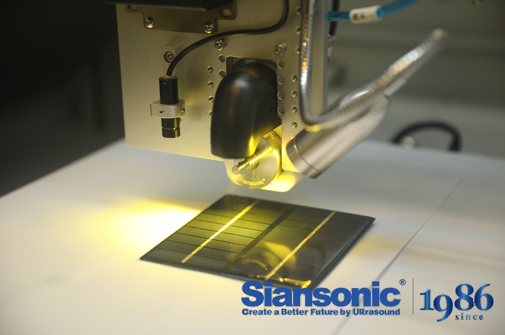
A nozzle that sprays clean water at room temperature might run for years without issue, but swap the fluid to a slurry with fine abrasive particles and the same component can erode past tolerance in days. Material choice is what separates a nozzle that outlives the system from one that needs constant replacement. Carbide and ceramic inserts, for example, routinely handle glass-filled polymers or metal powder suspensions that would chew through hardened stainless steel in under a week. The failure mode shifts from gradual wear to sudden loss of spray pattern accuracy, which then affects coating thickness, cooling uniformity, or atomization quality downstream.
Chemical attack is equally unforgiving. A brass nozzle in a mild acid stream may develop pitting and internal roughening long before any visible external damage appears, and that roughness disrupts flow long before leakage becomes obvious. PTFE or PVDF bodies resist many corrosive fluids but lack the mechanical strength needed for high-pressure drops, so engineers often end up with a compromise: a metal shell for structural integrity and a chemically resistant insert for the wetted surfaces. The trick is knowing which fluid properties actually drive degradation—some solvents will swell certain plastics, while others pass through without effect, and vapor-phase exposure above the liquid line can be more damaging than immersion.
There is no universal best material, only the right match for a specific set of operating conditions. A tungsten carbide nozzle might be overkill for filtered water, just as a hardened tool steel nozzle would be a poor choice for hot concentrated sulfuric acid. The real skill lies in identifying the dominant failure mechanism early enough to test alternatives before a production line experiences repeated unplanned downtime. Small-scale wear or corrosion coupons, or simply running two candidate nozzle materials side by side for a week, often reveals more than a supplier datasheet ever will.
Orifice Geometry Tweaks That Kill Edge Turbulence Without Killing Throughput
Sharp-edged orifice plates are notorious for shedding vortices right at the inlet lip, which shows up as edge turbulence, vibration, and a pressure signature that hurts downstream equipment. Simply rounding that lip by a fraction of the bore diameter—often just 5% to 8%—can keep the flow attached longer and delay boundary-layer separation without meaningfully changing the throat area. The result is less low-frequency rumble and fewer spin-up losses, yet the bulk flow rate stays essentially the same.
A more aggressive but still practical tweak is to cut a short chamfer on the upstream side instead of a full radius. This breaks the sharp corner into two milder angles, which spreads the pressure gradient over a longer path and suppresses the tight recirculation bubble that normally forms just inside the edge. Because the chamfer removes very little material, the effective opening and discharge coefficient remain close to the original design, so throughput is not sacrificed for smoother flow.
For applications where noise and turbulence are especially problematic, a tapered or elliptical contraction can be machined into the upstream face of the orifice. This contour guides the flow inward more gradually, reducing the abrupt acceleration that triggers edge separation. Tests often show turbulence intensity dropping by 40–60% with only a 1–2% change in flow capacity, proving that careful geometric tuning can kill edge turbulence while keeping throughput intact.
Drive Electronics: Why 'Good Enough' Piezo Matching Leads to Droplet Chaos
Most inkjet drive circuits treat piezo elements as if they are interchangeable. A tolerance of ±10% in capacitance or resonance looks acceptable on a datasheet, but at firing frequencies above 20 kHz that slack turns into measurable timing drift. One channel pushes a droplet at 6.2 m/s while its neighbor fires at 5.7 m/s, and the difference is enough to shift landing positions by several pixel widths after a few millimetres of flight.
The chaos starts small. A slightly under-driven piezo creates a tail that breaks into satellite droplets instead of merging cleanly. A slightly over-driven one slings fluid so hard that it bounces off the substrate or splatters around the nozzle plate. Because these mismatches are uneven across the head, you get moiré-like banding, color mixing errors, and random nozzle dropouts that no amount of printhead cleaning can fix. Operators blame the ink or the media, but the real culprit is the drive waveform assuming every piezo is identical.
Tight matching is not just a manufacturing luxury. Per-channel capacitance sensing, active damping, and waveform pre-distortion let the drive electronics compensate for the actual piezo in each nozzle. When the firing pulse is tuned to the real resonance of the transducer, the droplets stay uniform, the tail retracts cleanly, and the jetting becomes predictable. Skipping that step saves a few cents on passives and calibration, and pays it back in ruined prints and field returns.
Fluid Paths for Suspensions: Keeping Particles Moving Instead of Piling Up
Suspensions often fail not because the particles themselves are unstable, but because the flow geometry invites them to collide, slow down, and settle into a packed layer. A better approach is to shape the fluid pathway so that particles never get the chance to pile up. By designing channels with gradual tapers, helical twists, or strategically placed secondary flows, the suspension remains in constant motion, and the particles stay dispersed instead of accumulating on walls or dead zones.
The key is to treat the suspension as a living system where every turn and expansion affects particle trajectories. Sharp corners and sudden widenings create low-velocity pockets where heavier particles drop out. Replacing those with smooth, sweeping bends and maintaining a minimum shear rate throughout the flow keeps even dense particles tumbling along. In practice, this means mapping the path first with tracer particles or low-cost simulations, then modifying the geometry until no region shows prolonged residence time or bed formation.
What makes this design philosophy stand out is its focus on motion rather than additives or energy-hungry mixers. Instead of fighting sedimentation after it happens, you simply deny it a place to start. That shift in thinking leads to pipelines, reactors, and transfer lines that run longer between cleanings, handle higher solids loading, and avoid the performance fade that comes from a slowly building particle bed.
From Benchtop to Production Line: Designing Out Thermal Drift and Mechanical Chatter
Scaling a precision process from a controlled benchtop setup to a full production line rarely fails for the reasons people expect. The real culprits are usually two subtle, persistent forces: thermal drift and mechanical chatter. On the bench, a few degrees of temperature change or a slightly loose fixture might go unnoticed, but once you multiply cycle times, spindle speeds, and continuous operation, those small errors compound into scrap parts and unexplained variation. The first step is not chasing tighter tolerances on paper—it is measuring where heat actually accumulates in the machine structure, tooling, and workpiece, then designing passive or active compensation paths before the process ever leaves the lab.
Mechanical chatter is harder to eliminate by intuition alone. A toolholder that felt rigid during a five-minute test can become a resonant amplifier after eight hours of interrupted cuts. Production-minded design means mapping the system's dynamic stiffness across the actual operating envelope, not just at one sweet spot. This often leads to changes that look minor on a drawing but matter enormously in practice: shortening unsupported tool lengths, adding tuned mass dampers, adjusting spindle ramp profiles, or explicitly scheduling warm-up cycles so the entire line reaches thermal equilibrium before critical dimensions are cut.
The payoff comes when the same design language is applied to every station. Rather than treating drift and chatter as troubleshooting headaches, build them out through structured thermal management, fixture symmetry, and real-time feedback that only corrects for measured physical shifts—not operator guesswork. Lines designed this way hold tolerances longer, require fewer manual offsets, and produce data that is actually useful for predictive maintenance. From benchtop to production line, the goal is the same: make the process boring in the best possible way.
FAQ
Frequency directly influences the median droplet diameter—higher frequencies typically produce finer sprays, but the relationship isn't linear. For a custom design, you need to balance frequency against the liquid's viscosity and surface tension, because pushing beyond ~120 kHz can reduce throughput and increase risk of cavitation near the tip. It's often better to test at several frequencies with the actual formulation rather than relying on a universal formula.
The orifice should be shaped to minimize recirculation zones and dead volume where fluid can stagnate. A conical or exponential horn profile helps maintain a smooth velocity gradient, but for high-viscosity fluids you may need a wider throat and shorter tapered section to prevent clogging. Avoid sharp internal edges; even small burrs can seed premature droplet detachment and ruin spray uniformity.
Viscosity, surface tension, density, and solids content are the big four. Temperature dependence matters too—some formulations thin out dramatically when they warm up near the transducer. If the fluid contains particulates or dissolved gases, you'll also need to assess degassing requirements or the risk of erosion at the atomizing surface.
Because the nozzle's mechanical resonance shifts with temperature, liquid load, and even mounting torque. A custom design usually has a narrower bandwidth to maximize amplitude at the tip, so the driver must track resonance in real time rather than just output a fixed frequency. Without that feedback, you get amplitude drift, inconsistent atomization, and possible transducer overheating.
Keep the atomizing surface geometry identical during scale-up, and verify that the acoustic node position doesn't move. Small changes in horn length or mass distribution can tilt the spray cone or create side lobes. Using laser Doppler or high-speed imaging during pilot tests helps pin down the exact cone angle before committing to tooling. Also confirm that liquid feed pressure is low and steady—ultrasonic nozzles are not pressure atomizers.
Titanium alloys (like Grade 5) are a common starting point because they combine good acoustic properties with broad chemical resistance, but they can still pit in strong acids. For halide-containing fluids, consider a thin CVD diamond or silicon carbide coating on the atomizing tip. Just remember any coating changes the tip mass and stiffness, so re-tune the horn length afterward and validate amplitude uniformity.
Typically a single nozzle handles up to roughly 0.5–2 L/h without losing fine atomization, depending on viscosity. To go higher, you can cluster multiple nozzles on a common manifold rather than forcing more liquid through one tip, because exceeding the amplitude threshold causes large droplets and spitting. Maintaining laminar feed and keeping the liquid column in continuous contact with the atomizing surface are essential.
Conclusion
Custom ultrasonic nozzles rarely fail from a single bad choice—they fail because the interplay between frequency, droplet size, and flow rate gets locked into a spec sheet instead of treated as a live tuning problem. Crank the frequency up for finer droplets and you typically sacrifice flow rate; chase higher throughput and the median droplet diameter jumps. The only way out is to decide which parameter actually governs the coating, then design the nozzle around that priority. Material selection cuts just as deep. A nozzle made from the wrong alloy or polymer can outlast the fluid in one application and corrode through in a week in another, so chemical compatibility has to come before mechanical convenience. Orifice geometry is the next quiet lever: a small radius or a tapered exit can kill edge turbulence and stop satellite droplets without strangling the flow path.
Drive electronics get overlooked until the spray turns uneven. A 'good enough' match between the piezo driver and the nozzle resonance shifts with temperature and load, and that drift shows up as bimodal droplet distributions nobody asked for. If you are atomizing suspensions, the fluid path matters as much as the transducer. Sharp bends and dead zones let particles pile up, so gentle, continuously swept channels keep the slurry moving instead of settling into a clog. Moving from benchtop to a production line is where thermal drift and mechanical chatter stop being academic. Bolting a nozzle to a vibrating frame or letting it heat unevenly changes the resonance point mid-run, so the design has to include thermal compensation and damping from the start rather than as a retrofit.
Contact Us
Contact Person: Ivy Zhang
Email: [email protected]
Tel/WhatsApp: +86 1081502288
Website: https://www.siansonic.com/