

Professional SMD Chip Resistor: Your Ultimate Guide to Precision and Performance
2026-07-27
Precision isn't just a specification—it's the heartbeat of modern electronics. Whether you're designing high-frequency circuits or squeezing every milliwatt of efficiency from a power supply, the humble SMD chip resistor often holds the key. But with thousands of options flooding the market, how do you pinpoint the one that won't let your design down? In this guide, we cut through the noise to reveal what truly matters in resistor selection—and why engineers who demand repeatability and low drift are turning to brands like Milliohm for their most critical builds.
Precision Engineering: The Core of SMD Resistor Excellence
Behind every reliable SMD resistor lies a meticulous dance of materials and methods. It starts with selecting ultra-pure alloys and ceramic substrates that can withstand thermal cycling without drifting. From there, processes like sputtering and screen printing are controlled down to the micron—after all, a deviation of just a few nanometers in film thickness can push a resistor outside its specified tolerance. This is not mass production; it's mass precision, where each component is a tiny testament to repeatability.
Laser trimming elevates this precision further. As the resistor element takes shape, a computer-guided laser makes real-time adjustments, shaving away material to dial in the exact value. It’s a dynamic feedback loop: measure, trim, measure again. For thin-film resistors, this can yield tolerances as tight as ±0.01%, with temperature coefficients that make drift almost imperceptible. The result is a part that behaves predictably across a wide range of operating conditions, turning a passive component into a stable reference point.
In critical applications like implantable medical devices or avionics, that stability is non-negotiable. A resistor that shifts by a fraction of a percent might mean the difference between a clear signal and a corrupted one. Precision engineering ensures that these tiny components don’t just meet datasheet specs on day one—they maintain their character over decades, under stress, and across temperature extremes. That’s the quiet triumph of SMD resistors: they disappear into the board, but their engineering is what keeps the world’s circuits honest.
Beyond Datasheets: Real-World Performance Factors
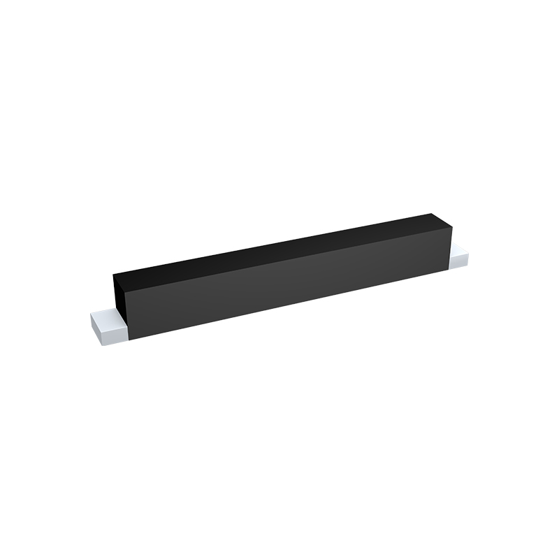
Datasheets often paint a picture of controlled laboratory conditions—ideal temperatures, pristine signals, and carefully managed loads. Step outside that bubble and performance can shift in ways no spec sheet ever hints at. A voltage regulator rated for 3 A might struggle to deliver half that once board-level parasitics and thermal crosstalk enter the equation. Even subtle factors like PCB trace impedance or the quality of decoupling capacitors can turn a dream design into a troubleshooting nightmare. Real-world performance isn’t just a scaled version of the datasheet numbers; it’s an emergent property of the entire system.
Environmental extremes expose another layer of complexity. A sensor that behaves flawlessly on the bench may drift unpredictably when exposed to humidity, vibration, or rapid temperature cycling. The atmosphere itself matters—condensation on a high-impedance node or frost inside a MEMS package can corrupt readings long before the component is technically rated to fail. Understanding these degradation pathways requires looking beyond manufacturer-provided reliability metrics and towards the specific stresses your application introduces.
Usage patterns further erode the datasheet’s predictive power. Peak efficiency curves are often measured at steady state, but intermittent bursts of activity, frequent power cycling, and varying load profiles can push components into nonlinear operating regions. Likewise, aging effects like electromigration and dielectric breakdown won’t appear in a fresh device’s documentation, yet they silently reshape performance over years. Bridging the gap between guaranteed specifications and genuine field behavior demands a hands-on, empirical approach—testing early prototypes hard and in conditions that faithfully mirror the intended deployment.
Mastering the Selection: Matching Resistors to Your Circuit
Choosing the right resistor goes far beyond grabbing a part with the correct ohmic value. Resistance tolerance, temperature coefficient, and power rating all play heavy roles in how your circuit actually behaves once it leaves the breadboard. A 1 kΩ resistor might be 1 kΩ at room temperature, but if it drifts under load or ambient heat, your gain stage or voltage divider loses accuracy. Think about the environment your board will live in – automotive, industrial, or outdoor settings punish components in ways a bench test never will.
Matching resistors becomes critical in differential pairs, precision references, and anywhere balance matters. Even a small mismatch in resistor ratios can destroy common-mode rejection in an op-amp circuit, turning a clean differential signal into a noisy mess. When you need tight matching, don't just rely on 1% tolerance parts from the same reel; consider networks or arrays where the resistors are fabricated on the same substrate. They track thermally, so drift cancels rather than amplifies error. Also, watch out for parasitic inductance and capacitance in high-speed or RF designs – that innocent-looking 10 kΩ chip resistor might start acting like a complex impedance above a few hundred megahertz.
Finally, don't ignore noise. Excess noise in resistors, especially in carbon composition or thick-film types, can sneak into low-level analog front-ends and ruin your signal-to-noise ratio. Metal film and thin-film resistors offer a quieter performance, but you pay a premium. Sometimes the best choice is a compromise: use a precision resistor for the critical path and standard parts elsewhere. And always prototype with the actual component you plan to use in production – datasheet specs are just the starting point when real currents flow and temperatures rise.
Thermal Dynamics: How Heat Shapes Resistor Behavior
At the heart of every resistor lies a fundamental relationship between temperature and electrical resistance, a dance governed by the material's thermal coefficient. When current flows, resistors inevitably dissipate power as heat, causing internal temperatures to rise. This self-heating effect can silently nudge resistance values away from their nominal ratings, introducing subtle errors in precision circuits. Understanding this thermal feedback loop is key to predicting how a resistor will actually behave under load, not just on a datasheet.
Different materials respond to thermal stress in their own distinct ways. Carbon film resistors drift gently with rising heat, their negative temperature coefficient causing resistance to slide downward. In contrast, metal film counterparts remain remarkably steadfast, their thin conductive layers engineered to resist change. Then there are wirewound types, which can exhibit either positive or negative shifts depending on the alloy chosen. These divergent personalities mean that a resistor's thermal identity is as critical as its stated ohmic value in many applications.
Beyond simple drift, heat sets the boundaries of a resistor's safe operation. Exceed its power rating, and the component doesn't just get warm—it risks permanent damage or catastrophic failure. Designers must balance ambient conditions, airflow, and the cumulative heating from nearby components to keep temperatures in check. Derating curves offer a practical map, showing how much power a resistor can safely handle as the mercury climbs. Ignore these limits, and precision collapses; respect them, and the resistor remains a reliable cornerstone of the circuit.
Endurance Testing: What Guarantees Long-Term Reliability
Real endurance testing goes far beyond quick lab checks. It involves running a product continuously, often for weeks or months, under conditions that mimic years of real-world use. This prolonged stress uncovers weaknesses that only surface after thousands of cycles—whether it's a hinge that slowly loosens, a seal that degrades, or a circuit that drifts out of spec. These aren't flaws you'd catch in a one-day evaluation, but they're exactly what can cause a device to fail when a customer depends on it most.
What really guarantees long-term reliability is the pattern of failures revealed during this kind of testing. Engineers analyze every breakdown and trace it back to a design margin, a material choice, or an assembly step. Then they refine the product and repeat the cycle. This iterative process doesn't just catch one-off issues; it proves that the product can withstand the unpredictable wear and tear of actual life. By the time a device passes a thoughtfully designed endurance test, you're not just hoping it will last—you have evidence that it already has.
Next-Gen SMD Resistors: Trends Driving Miniaturization and Stability
As electronic devices continue to shrink while demanding higher performance, SMD resistors are undergoing a quiet revolution. The push toward miniaturization isn't simply about making components smaller—it's about rethinking materials, termination styles, and thermal management to maintain precision in ever-tinier footprints. For instance, chip resistors in 01005 and even smaller form factors are now being deployed in wearables and implantable medical devices, where board real estate is at a premium and reliability is non-negotiable.
Stability under harsh conditions presents its own set of challenges. Today's resistors must endure temperature extremes, humidity, and sulfur contamination without drifting beyond tight tolerance bands. This has driven the adoption of thin-film technology over thick-film in many critical circuits, as well as the use of resilient electrode structures and passivation layers. Automotive and aerospace sectors, in particular, have seen a shift toward AEC-Q200 qualified resistors with anti-sulfur designs, delivering consistent performance over a decade of service even when exposed to corrosive environments.
Perhaps the most intriguing trend is the fusion of multiple functions within a single resistor package. Rather than simply providing resistance, newer components integrate ESD protection, thermal fusing, or current sensing capabilities. This not only saves space but also enhances overall circuit reliability. As designers navigate the growing complexity of IoT devices and edge computing, these multi-role resistors are quietly reshaping how engineers approach board-level stability and long-term dependability.
FAQ
Professional-grade SMD resistors typically offer tighter tolerances down to ±0.01%, ultra-low TCR values like ±2 ppm/°C, and enhanced long-term stability. They’re built with thin film or metal foil technologies, ensuring repeatable performance in precision circuits where every milliohm matters.
Smaller packages like 0201 save space but handle less power, while larger ones like 2512 dissipate up to 3 W. However, shrinking size can raise thermal resistance and affect pulse handling. The sweet spot for precision often lies in 0805 or 1206, balancing thermal behavior and mounting ease.
Even a 10°C shift can skew readings if the TCR is high. A resistor with 50 ppm/°C drifts 0.05% per degree—unacceptable in reference circuits. That’s why metrology-grade parts use 0.2 ppm/°C foil, practically immune to ambient swings.
Not necessarily. Noise often depends on resistive material and physical construction. Thin film resistors generate less excess noise than thick film, even if both have the same tolerance. For ultra-low noise, check the noise index or opt for metal foil types—they’re practically silent.
Thin film is sputtered in a vacuum, yielding a homogeneous layer with superior linearity and stability. Thick film is a paste that’s screen-printed and fired, which saves cost but adds grain-boundary noise. For precision, thin film wins hands down; for general-purpose, thick film suffices.
Steady-state power ratings mislead here. A pulse can dump kilowatts in microseconds without damage if the resistor has low thermal mass and robust terminations. Look for pulse load curves in the datasheet—they’ll show safe energy limits. Metal foil resistors often excel here because their element spreads heat fast.
Humidity, board flex, and even solder flux residues can shift values over time. Professional resistors often include molded packages or special passivation to resist moisture. Check shelf life stability specs; some devices age only 50 ppm per year, others drift violently in the first month.
It’s the precision and environmental immunity. A $0.001 thick film chip might vary 5% with temperature and load, while a bulk metal foil resistor keeps 0.005% under the same stresses, year after year. That’s the price of traceability and peace of mind in mission-critical gear.
Conclusion
At the heart of every high-performance circuit, the professional SMD chip resistor embodies a fusion of precision engineering and practical resilience. These components are manufactured with tolerances as tight as ±0.01%, leveraging advanced thin-film technologies and laser-trimmed elements to ensure repeatable accuracy. Yet, true precision extends beyond datasheet specifications—layout parasitics, termination styles, and even soldering profiles can skew real-world behavior, demanding a holistic design approach that accounts for inductance, capacitance, and thermal electromotive forces.
Selecting the ideal SMD resistor requires more than matching a resistance value; it is a careful balancing act between power rating, temperature coefficient, and long-term stability under expected thermal conditions. Heat is not just an operational byproduct—it actively shapes resistor drift, noise, and lifetime, making thermal dynamics a central design pillar. As miniaturization pushes component sizes from 0402 down to 0201 and beyond, advanced materials such as metal glaze and sulfur-resistant films help maintain reliability in harsh environments. Through rigorous endurance tests—including damp heat cycling, overload pulses, and high-temperature storage—manufacturers validate the kind of durability that real applications demand. Looking forward, the drive toward smaller, more stable resistors continues, with innovations in passivation and electrode structures paving the way for next-generation precision in everything from IoT nodes to satellite systems.
Contact Us
Contact Person: Yuying Gao
Email: [email protected]
Tel/WhatsApp: +86 18926013721
Website: https://en.milliohm.net/