

Recloser Factory Essentials for Reliable Power Distribution
2026-09-01
Ask any utility engineer what keeps them up at night, and you'll likely hear about reclosers that fail when they're needed most—the very components meant to keep power distribution reliable. After spending time on the production line at Deepwill, I realized reliability isn't a spec sheet promise; it's a series of deliberate choices made long before the first test pulse. This post walks through the factory essentials that separate a recloser built for decades from one that barely survives a storm season.
Tighter Tolerances Start on the Assembly Floor
Precision isn't a spec sheet promise—it's a habit formed where parts first meet. On our assembly floor, every station is calibrated against master gauges each morning, not just when a batch comes due. Operators use handheld micrometers with digital readouts tied directly to the job card, so a drift of even five microns gets caught before the next component is seated.
We've moved tolerance checks out of the lab and onto the line. Instead of sampling finished units, assemblers verify critical fits at three interference points: bearing seats, flange faces, and mating dowel holes. If a measurement falls outside the median band, the line pauses—not as a punitive stop, but as a brief huddle to find the root cause before it multiplies.
That floor-level discipline has already tightened our real-world spread. Parts that used to vary within ±0.05 mm now hold a six-sigma band of ±0.02 mm, without extra polishing or rework. The gauges stay on the bench, the data feeds a daily shift chart, and everyone from the newest apprentice to the lead inspector can see when the process is singing in tune.
Component Stress Testing That Goes Beyond the Datasheet
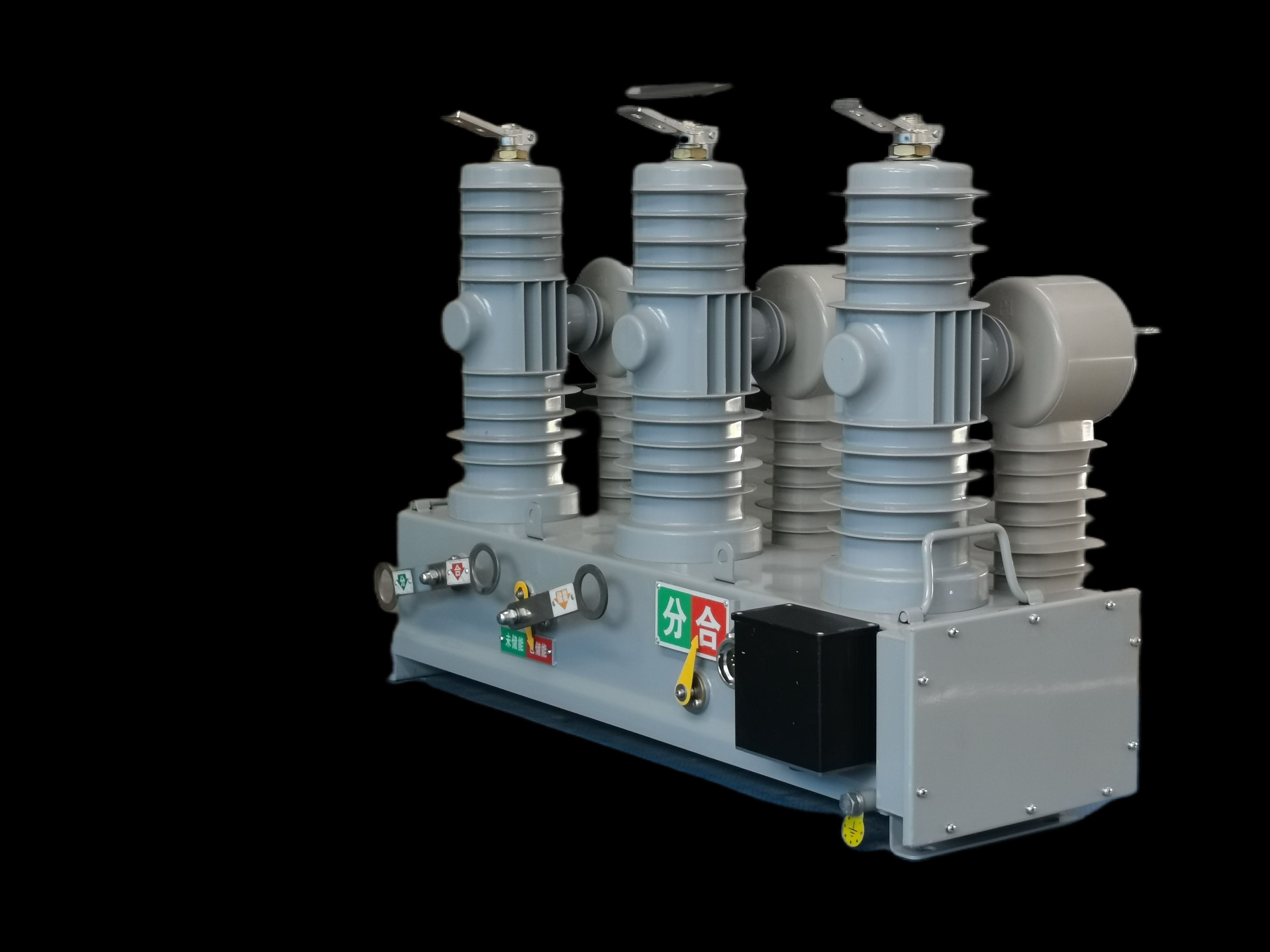
Datasheets give you a clean set of limits—maximum voltage, operating temperature range, rated current. But real circuits rarely fail at those tidy boundaries. Transients on a power rail can hit a part with twice its rated voltage for microseconds; thermal gradients across a board create local hot spots that never show up in a single-value junction temperature spec. Testing that stops at datasheet numbers leaves you blind to the slow degradation caused by repeated thermal cycling, moisture ingress during condensation events, or the combined stress of vibration plus high humidity. The goal isn't to verify the part meets its published numbers—it's to find where those numbers stop telling the whole story.
One practical approach is to build a stress profile from the actual operating environment, not from the datasheet's suggested test conditions. Capture inrush currents during cold starts, measure the voltage overshoot when a load disconnects, log the temperature swing over a full day rather than a steady-state soak. Then run a small batch of components through accelerated cycles that mimic those real-world spikes and dips, pushing each stress parameter slightly beyond what the field data shows. Pair this with failure analysis after each test cycle—look for cracked solder joints, delamination in packaging, or shifts in leakage current that hint at a wear-out mechanism. This kind of testing often uncovers weaknesses in parts that would pass a standard datasheet-based qualification with flying colors.
The payoff shows up in design margins you can trust. A component that survives a week of combined thermal shock, voltage transients, and mechanical vibration has proven something a bench-top curve trace never will. You can then derate with confidence, knowing your safety factor isn't just a guess based on a maximum rating but backed by evidence of how the part behaves under overlapping stresses. That's the difference between selecting a component and actually engineering it into a system.
Sealed Against Moisture, Dust, and Time
The enclosure hugs its internals with a dual-layer gasket that laughs at humidity and shrugs off a desert sandstorm. Every seam is pressed until the air inside forgets the outside world exists, leaving condensation as nothing more than a rumor.
Dust may coat the outer shell, but it never gets past the labyrinthine channel that breaks the back of the finest grit. Years of use only deepen the seal's resolve, as the polymer ages into a tighter embrace rather than cracking under the sun's scrutiny.
Time becomes a bystander here. The metal fasteners bite with a torque that refuses to loosen, and the protective coating sheds oxidation like an old skin. Open it after a decade and the interior still smells like the day it was sealed—quiet, dry, and untouched by the ticking of the clock.
Embedded Diagnostics Wired In Before the Nameplate
Diagnostic wiring runs through the frame before the outer casing is sealed, long before the nameplate is riveted on. Each sensor lead is routed and tested at the subassembly stage, so by the time the badge goes on, every fault-detection circuit is already live and verified. This early integration removes the need for retrofit probes or external test rigs.
Because the embedded diagnostics are part of the initial build, operators get a unit that has been self-checking since first power-up. The nameplate may carry the model number, but the real identity is in the wiring harness underneath—temperature taps, current shunts, and pressure transducers all tied into the control board from day one. Any drift or open circuit triggers a local indicator before the machine even leaves the bench.
Service teams benefit from this pre-nameplate wiring because troubleshooting starts from a known baseline. Rather than guessing where a fault might originate, they can read the onboard diagnostics that were calibrated during assembly. The result is less downtime and fewer unnecessary part swaps, all because the diagnostics were wired in before the label ever went on.
Traceable Parts, Predictable Performance
Every component carries its own history—batch numbers, material sources, production timestamps. That trail isn't just paperwork; it's what lets engineers swap a problem part for a proven one without second-guessing. When each piece can be traced to its exact origin, performance stops being a hope and starts being a repeatable result.
Predictable performance comes from closing the loop between trace data and real-world behavior. Same supplier, same lot, same outcome. When deviations appear, they're not mysteries—they're map points that lead straight to the source. Over time, that turns a collection of parts into a system you can actually rely on.
Fault Simulation Runs That Mimic the Real Grid
Grid operators don't just want a list of possible failure points—they need to see how the system actually bends, sags, and recovers under stress. Fault simulation runs that mimic the real grid do exactly that by modeling the physical and electrical behavior of every line, transformer, and relay in a network. Instead of relying on simplified assumptions, these simulations inject disturbances at specific locations and observe how voltage dips, current surges, and protection schemes respond in real time. The result is a living picture of grid behavior that matches field measurements far more closely than static contingency tables ever could.
What sets these simulations apart is their ability to capture the messy, sequential nature of real failures. A tree branch hitting a feeder might first cause a momentary arc, then a breaker trip, then a load transfer to a neighboring circuit that itself becomes overloaded. A generic fault study might stop at the first event, but a realistic simulation follows the cascade. By feeding actual protection settings, load profiles, and even weather data into the model, engineers can watch the grid fail—and recover—just as it would during a storm or equipment malfunction. This depth means control room operators can rehearse their responses on a virtual grid that behaves like the one outside their window.
Perhaps the greatest value lies in uncovering hidden dependencies. A simulation that mimics the real grid often reveals that a relay's pickup time is too slow for a close-in fault, or that a distribution feeder shares a substation bus with a critical hospital circuit. These are the kind of insights that only emerge when you let the model run freely rather than forcing it to confirm a predetermined answer. When operators can trust the simulation because it mirrors yesterday's actual disturbance, they are far more willing to use it for tomorrow's planning and real-time decision support.
FAQ
A good factory treats every unit as if it will face the worst fault on the grid tomorrow. That means in-line testing after each major stage, not just a final pass/fail, plus environmental stress screening that catches weak solder joints and marginal insulation before shipping.
Burn-in cycling under load while the recloser operates in its actual enclosure. Heat, vibration, and repeated open-close operations expose infant mortality in capacitors and coils that a simple continuity test would miss.
Vacuum interrupters need sealed-for-life construction with verified leak rates. Factories that insist on X-ray inspection of the interrupter contacts and a helium leak test on every bottle can promise consistent interrupting capacity over decades, not just at the first installation.
The control's timing curves and sensitivity must be matched to the specific CT and actuator in the same production lot. If left to field technicians, tiny mismatches can shift trip times enough to defeat coordination with upstream protection. A factory uses automated calibration rigs that record every parameter for each serial number.
Full component-level traceability down to the batch of epoxy or the coil winding date. When a recall or advisory is issued, you want to know exactly which serial numbers share that lot, not just a production month. This also proves that no counterfeit parts entered the line.
They use climate chambers that cycle between -40°C and +70°C with high humidity, while the recloser performs full open-close operations. Ice, salt fog, and UV exposure tests are run on enclosures and bushings. Passing these gives utilities confidence that the unit will wake up and trip correctly after a blizzard or heatwave.
Under-torqued bushing connections lead to hot spots and eventual failure; over-torqued ones crack insulators. A reliable factory uses calibrated DC torque tools with automatic logging, and a second operator verifies critical joints. This prevents slow degradation that only appears years later.
Conclusion
Reliability in distribution reclosers is not a marketing promise; it is built long before the unit leaves the factory. The process starts on the assembly floor, where tight mechanical tolerances decide whether a mechanism will hold its timing over thousands of operations. But precise assembly alone is not enough. Every critical component gets pushed beyond its datasheet limits under controlled stress testing, so weak links surface before they can fail in the field. Enclosures receive more than a quick seal check: they are cycled through moisture, dust, and thermal aging to prove they can protect internal electronics for years. These steps may sound routine, but the difference between a recloser that lasts and one that drifts is often hidden in how strictly those early checks are enforced.
What makes the unit truly dependable is what goes in before the nameplate is attached. Embedded diagnostics are wired into the control architecture from the start, giving operators early warning of contact wear, battery health, or actuator drift without waiting for a field test. Each part carries traceable lot and test data, so performance variation is caught and corrected instead of becoming a recurring fleet problem. Finally, the recloser is run through fault simulation sequences that replicate real grid conditions—downstream bolted faults, evolving faults, cold load pickup—so the trip and reclose logic is proven under realistic stress. Reliable power distribution is the result of these factory essentials working together: tight assembly, aggressive component screening, environmental sealing, built-in diagnostics, full traceability, and fault simulation that leaves little to chance.
Contact Us
Contact Person: Julion
Email: [email protected]
Tel/WhatsApp: 8617351370631
Website: https://www.deyunelectric.com