

Thermoforming Die Making Equipment Solutions for High-Precision Mold Production
2026-11-02
The difference between a good thermoformed part and a great one often comes down to the die—and the equipment that built it. ADEWO delivers thermoforming die making equipment solutions designed for high-precision mold production, helping you avoid the small errors that lead to big scrap rates. Here’s what to look for when every micron counts.
Micron-Accurate Machining That Eliminates Hand Finishing
Achieving micron-level tolerances used to require a separate bench operation: a machinist would take the part off the CNC, inspect it under magnification, and spend minutes or hours hand-stoning, polishing, or deburring. Modern machining centers with high-resolution encoders, balanced spindles, and adaptive toolpath control now produce surfaces clean enough to skip that step entirely. The result is a part that goes straight from the machine to final inspection—or directly into assembly.
The key lies in controlling the entire cut rather than fixing the result afterward. By using dynamic tool compensation, vibration damping, and micromachining strategies optimized for specific materials, shops can hold form and position tolerances within ±1 micron while maintaining a burr-free edge. This removes the variability that hand finishing introduces, especially on intricate geometries where a human hand can’t reliably reach the same corner twice.
For components like hydraulic valve seats, orthopedic implants, or microfluidic molds, eliminating hand work shortens lead times and reduces scrap. More importantly, it makes the surface finish repeatable across hundreds or thousands of parts. What once depended on the skill of an individual finisher now lives in the CAM file and the machine’s thermal stability, so the first part and the last part come out with the same micron-accurate surface.
Thermal Design Beyond Drilling Cooling Lines
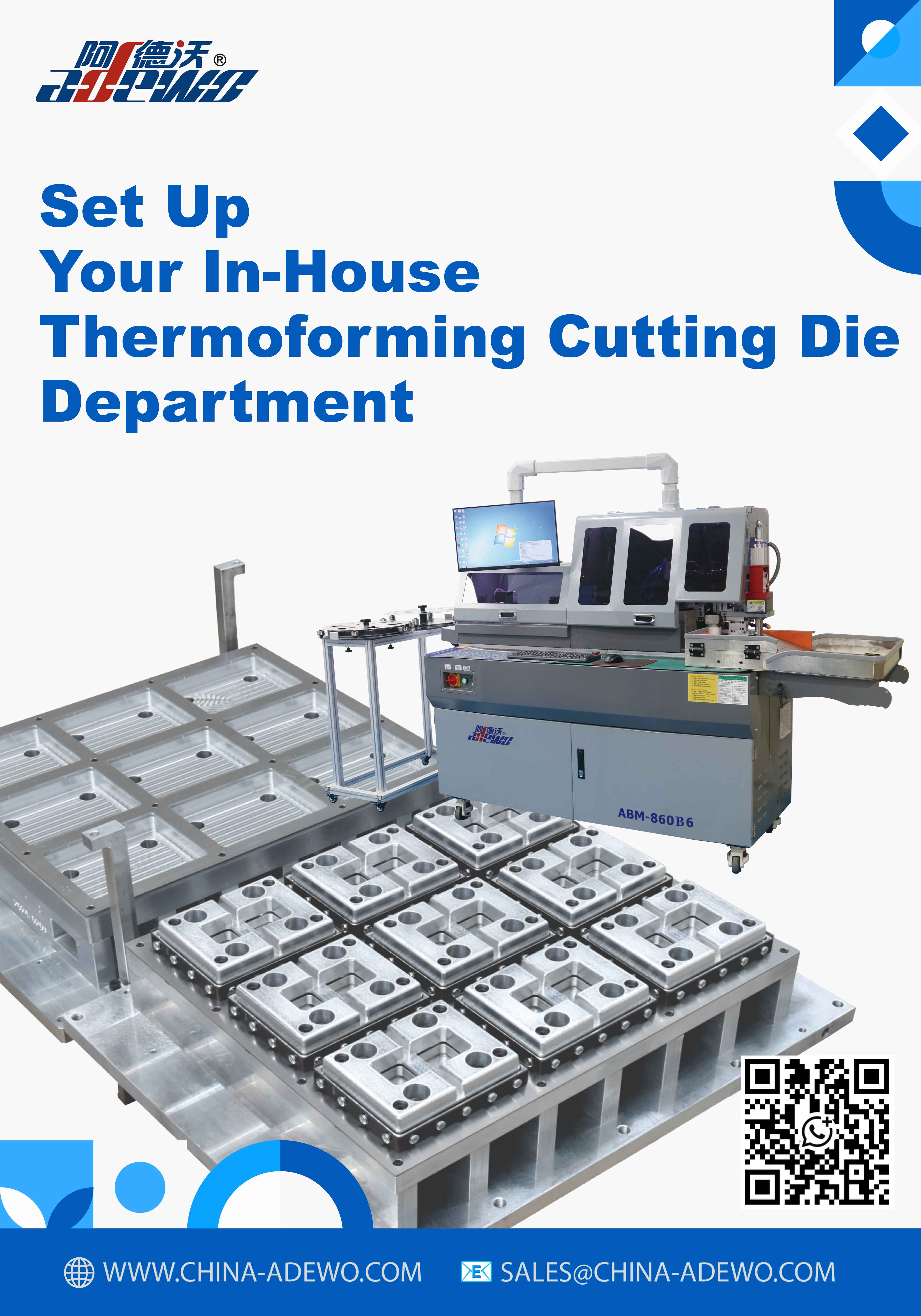
Standard cooling lines often fall short once you push beyond conventional mold temperatures and cycle times. Rather than simply adding more drilled channels, modern thermal design starts with mapping the heat load distribution across the part geometry. This means identifying thick sections, rib intersections, and sharp corners where heat concentrates, then treating those areas as individual thermal zones. Instead of uniform water flow, you might vary channel diameters, use baffles or bubblers only where needed, or shift to conformal cooling that follows complex surfaces without sacrificing mold strength.
Beyond the physical channels, materials and interfaces play a bigger role than most realize. High-conductivity inserts made from copper alloys or even vapor chambers can bridge the gap between a curved part surface and a straight drilled line. Thermal interface pastes or soldered joints often outperform press-fit inserts, reducing contact resistance that silently adds seconds to every cycle. In tight cores or thin blades, heat pipes or liquid-cooled pins become practical alternatives where a drilled passage would weaken the tool or simply cannot fit.
Finally, thermal design must account for the entire cycle, not just the cooling phase. Preheating zones with cartridge heaters or pulsed cooling can flatten the temperature swing between injection and ejection, reducing warpage without extra cooling time. Sensors embedded near the cavity surface allow real-time adjustment of flow rates based on actual mold temperature, turning cooling from a fixed plumbing layout into an active control strategy. The goal is not colder steel, but a more uniform and predictable heat removal path that shortens cycles while improving part quality.
Tool Steel Selection for Consistent Part Release
Part release problems in injection molds rarely appear on the first shot. They develop as the cavity surface changes—micro-pitting, galling, and corrosion all increase the force needed to eject a part. Tool steel selection should therefore focus on long-term surface stability rather than just initial hardness. A grade that holds a fine polish and resists adhesion under repeated contact with hot polymer will keep ejection consistent for far more cycles than a harder but less stable option.
For cores and inserts that face high friction or textured surfaces, a high-chromium stainless mold steel often outperforms standard H-13, especially with glass-filled or flame-retardant resins. The chromium content reduces micro-welding between the plastic and the steel, while a proper heat treatment keeps the surface from deforming under clamp pressure. If sticking persists, a thin PVD coating like chromium nitride or diamond-like carbon can be applied, but the base steel still determines how well that coating adheres and how evenly it wears.
The best approach pairs steel choice with ejection geometry and cooling layout. Draft angles and ejector placement only work if the cavity surface remains smooth and chemically stable. Track which steel grades have worked for specific part geometries and resin families in your shop; that history is often more useful than a generic datasheet. When release force starts to climb after a mold has been in production, look at the steel's surface condition before increasing ejection stroke or adding more knockouts.
In-Process Metrology for Sub-Micron Cavity Drift
Keeping a sub-micron cavity from drifting during machining or assembly is rarely a single measurement problem. Off-line checks after the fact miss the thermal settling, stress relaxation, and clamping shifts that happen while the part is still in the fixture. In-process metrology closes that gap by embedding sensing directly into the setup, so the cavity length, roundness, or tilt is tracked continuously rather than sampled between steps.
The most practical approaches pair low-coherence interferometry or chromatic confocal probes with a stable reference surface mounted near the cavity. These tools can resolve changes of a few nanometers through a viewport or fluid film, which is essential when the cavity is being lapped, polished, or actively temperature-cycled. Because the measurement is inline, it becomes possible to separate reversible thermal expansion from actual material removal or irreversible creep, giving the operator a clearer picture of what is really moving.
Making this work outside a metrology lab usually means simplifying the fixture and accepting that the reference itself will drift. A common trick is to use the workpiece as its own reference at the start of a cycle and measure only relative change, then correct with a periodic touch-off against a calibrated artifact. The feedback loop can then adjust feed rates, dwell times, or local heating before the drift exceeds a few tens of nanometers, which keeps the cavity within tolerance without stopping the process for a full inspection.
Automated Polishing for Optical-Grade Mold Surfaces
Getting a mold surface to optical grade by hand takes weeks and still leaves room for inconsistency. Automated polishing changes that by pairing force-controlled spindles with in-situ surface measurement. The machine adjusts dwell time and abrasive pressure on the fly, so a freeform lens cavity doesn't get over-polished at the edges while the center lags behind.
One of the harder problems is keeping form error within a fraction of a wavelength while still removing tool marks from the previous milling step. A purely position-based robot arm tends to fight the part's curvature. Better results come from hybrid systems that mix compliant tooling with periodic interferometric checks, letting the controller decide whether to switch from a hard felt lap to a softer polyurethane pad based on local slope changes.
For mold shops, the payoff isn't just speed. Automated runs generate a traceable record of pressure, speed, and surface finish at each coordinate, which matters when a customer asks why a particular cavity deviates by 20 nanometers. That kind of closed-loop data also feeds back into the next toolpath, so the second mold off the line often needs less correction than the first.
Shrinkage Compensation Tuned to Actual Material Behavior
Relying on a single generic shrinkage value for every batch of the same polymer is a common source of dimensional drift. Actual behavior shifts with filler content, regrind ratio, moisture level, and even the specific lot of resin delivered that month. When the compensation factor is tied to measured data from the material currently running in the press, the predicted cavity dimensions stop being an approximation and start matching what the part will really do after ejection and cooling.
Practical tuning begins with molding a standardized test plaque or a short-run of the actual part geometry at the intended process window. Measuring length, width, and thickness in both flow and cross-flow directions exposes anisotropy that a single shrinkage number can never capture. Those measured values, logged against melt temperature, pack pressure, and cooling time, build a small dataset that reflects how this specific lot of material moves. From there, the compensation can be adjusted per axis or per critical feature rather than applied as a uniform scale factor.
Once the compensation is anchored to real measurements, the usual cycle of cut-and-try tool modifications shrinks dramatically. A toolmaker may still leave a small amount of steel-safe stock on high-risk features, but the initial dimensions land far closer to tolerance. When the next material delivery arrives with a slightly different melt flow index, the same measurement routine quickly reveals whether the compensation needs a minor shift. This closes the loop between material reality and tool geometry, reducing both scrap and the time spent chasing dimensions on the shop floor.
FAQ
Core machines include CNC milling centers with thermal compensation, high-speed graphite milling machines for electrode production, wire EDM for fine details, and precision surface grinders to achieve flatness within microns. Each piece plays a specific role in maintaining the tight tolerances required for mold cavities.
Advanced 5-axis CNC machining combined with EDM allows manufacturers to cut deep ribs, sharp corners, and undercuts that would be impossible with traditional 3-axis methods. The software simulates tool paths to avoid collisions and ensures consistent material removal without compromising the die surface.
Thermoforming dies need uniform heating and cooling channels to prevent warping and ensure consistent part wall thickness. Precision gun-drilling and conformal cooling channel designs help maintain thermal stability, which directly impacts the repeatability of formed parts.
After machining, dies often undergo hardened steel polishing, diamond lapping, or chemical mechanical polishing. The exact method depends on the polymer being formed; for clear or glossy products, a surface roughness below Ra 0.05 microns is often required to avoid optical defects.
Coordinate measuring machines (CMMs) and laser scanning systems verify every critical dimension against the CAD model. In-line inspection during production identifies deviations early, allowing corrective action before the die is completed, which reduces scrap and rework time.
Yes, modular CNC workholding and quick-change pallet systems allow the same machining centers to switch between single prototype dies and multi-cavity production tools. This flexibility helps shops meet short lead times without sacrificing accuracy.
Aluminum alloys like 7075 are popular for short runs due to easy machinability, while hardened tool steels like P20 or H13 are used for long production. Machining centers with high-torque spindles and rigid frames handle both, but cutting parameters and tool coatings are adjusted to prevent built-up edge and extend tool life.
Robotic loading systems and palletized CNC cells enable unattended machining, which reduces human error and maintains tight tolerances across multiple shifts. Automated tool presetting and broken-tool detection further ensure that each die component is produced to the same standard.
Conclusion
Achieving high-precision thermoforming dies demands more than conventional machining centers; it calls for equipment built around micron-accurate cutting paths that render manual hand finishing obsolete. Our solutions integrate dedicated thermal management strategies that move beyond simple drilled cooling lines, using conformal channels and thermally tuned inserts to stabilize temperatures across the forming surface. The selection of tool steel is equally deliberate, matched to polymer release behavior and wear resistance, so parts eject consistently without sticking or surface drag.
In-process metrology systems track cavity geometry in real time, flagging sub-micron drift before it compromises part consistency, while automated polishing routines produce optical-grade surface finishes that eliminate repetitive manual labor. Crucially, shrinkage compensation is not a fixed offset; it is derived from actual material behavior under production conditions, allowing the die to account for local thickness variations and cooling gradients. Combined, these equipment capabilities deliver molded parts that meet tight dimensional tolerances without iterative rework or excessive tryout cycles.
Contact Us
Contact Person: KAELYN LEE
Email: [email protected]
Tel/WhatsApp: +86 15012673758
Website: https://www.china-adewo.com